


Question
Medium
Solving time: 3 mins
Draw a labelled diagram of a full wave rectifier circuit. State its working principle. Show the input-output waveforms.
Views: 5,954 students
Found 6 tutors discussing this question
Discuss this question LIVE
7 mins ago
 Text solution
 Verified
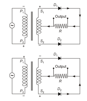
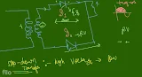
Full-wave rectifier: The circuit diagram of a full-wave rectifier is shown in figure. The a.c. to be rectified is fed to the primary terminals of a centre-tapped transformer.
During the first (positive) half cycle of the a.c. input, the upper end of the secondary coil acquires positive potential and the lower end acquires negative potential. As a result, diode gets forward biased and diode gets reverse biased. Diode conducts and a current flows through load, as shown by continuous in Figure.
During the next (negative) half cycle of the a.c. input, the upper end of the secondary coil acquires negative potential and the lower end acquires positive potential. As a result, diode gets reverse biased and diode gets forward biased. Diode conducts and a current flows through load, as shown by dotted lines in figure. The direction of current remains same as in the previous half cycle.
The circuit diagram of full wave rectifier is shown below.
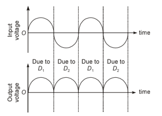
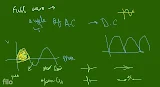
The input and output waveforms have been given below.
During the first (positive) half cycle of the a.c. input, the upper end of the secondary coil acquires positive potential and the lower end acquires negative potential. As a result, diode gets forward biased and diode gets reverse biased. Diode conducts and a current flows through load, as shown by continuous in Figure.
During the next (negative) half cycle of the a.c. input, the upper end of the secondary coil acquires negative potential and the lower end acquires positive potential. As a result, diode gets reverse biased and diode gets forward biased. Diode conducts and a current flows through load, as shown by dotted lines in figure. The direction of current remains same as in the previous half cycle.
The circuit diagram of full wave rectifier is shown below.
The input and output waveforms have been given below.
Was this solution helpful?
41
Share
Report
Filo tutor solutions (3)
Learn from their 1-to-1 discussion with Filo tutors.
6 mins
Uploaded on: 4/4/2022
Connect instantly with this tutor
Connect now
Taught by

Ritvik Singh
Total classes on Filo by this tutor - 5,273
Teaches : Physics, Mathematics, Physical Chemistry
Connect instantly with this tutor
Notes from this class (3 pages)

Was this solution helpful?
146
Share
Report
7 mins
Uploaded on: 4/13/2022
Connect instantly with this tutor
Connect now
Taught by

Abhay
Total classes on Filo by this tutor - 371
Teaches : Physics
Connect instantly with this tutor
Notes from this class (2 pages)
Was this solution helpful?
66
Share
Report


One destination to cover all your homework and assignment needs
Learn Practice Revision Succeed

Instant 1:1 help, 24x7
60, 000+ Expert tutors

Textbook solutions
Big idea maths, McGraw-Hill Education etc

Essay review
Get expert feedback on your essay

Schedule classes
High dosage tutoring from Dedicated 3 experts
Practice more questions from Semiconductor Electronics: Materials, Devices and Simple Circuits
Question 1
Easy
Views: 5,967
Question 2
Medium
Views: 5,621
Question 4
Easy
Views: 5,508
Practice questions on similar concepts asked by Filo students
Question 1
Views: 5,128
Question 2
Views: 5,112
Question 3
Views: 5,586
Question 4
Views: 5,520


Stuck on the question or explanation?
Connect with our Physics tutors online and get step by step solution of this question.
231 students are taking LIVE classes


| Question Text | Draw a labelled diagram of a full wave rectifier circuit. State its working principle. Show the input-output waveforms. |
| Updated On | Apr 13, 2022 |
| Topic | Semiconductor Electronics: Materials, Devices and Simple Circuits |
| Subject | Physics |
| Class | Class 12 |
| Answer Type | Text solution:1 Video solution: 3 |
| Upvotes | 323 |
| Avg. Video Duration | 6 min |
